Retro Raycasting game - part 1
A few weeks ago I wanted to code a 3d video game in C++. To share my experience, I decided to write about the rendering technique I used.
To make you enjoy my game (still in development) I compiled it with emscripten which gives an executable in webassembly! Feel free to play it here.
Raycasting is a rendering technique to create a 3D perspective from a 2D world. Many years ago when computer were slower it wasn’t possible to run 3D engines in realtime for games. In 1991, Hovertank 3D, the very first game that implement the raycasting technique, released. A year after in 1992, the famous Wolfenstein 3D launched the FPS hype thanks to raycasting.
The strength of the method is that it only requires the rendering calculation to be performed on each vertical line of pixels on the screen. Rendering textured floor or ceiling is more expensive though.
The Basic Idea
The principle of the raycasting method is to start from a 2-dimensional world represented as a grid. Each square of the grid can either be a wall or an empty space. The player, on the other hand, is modeled as a point on this grid.
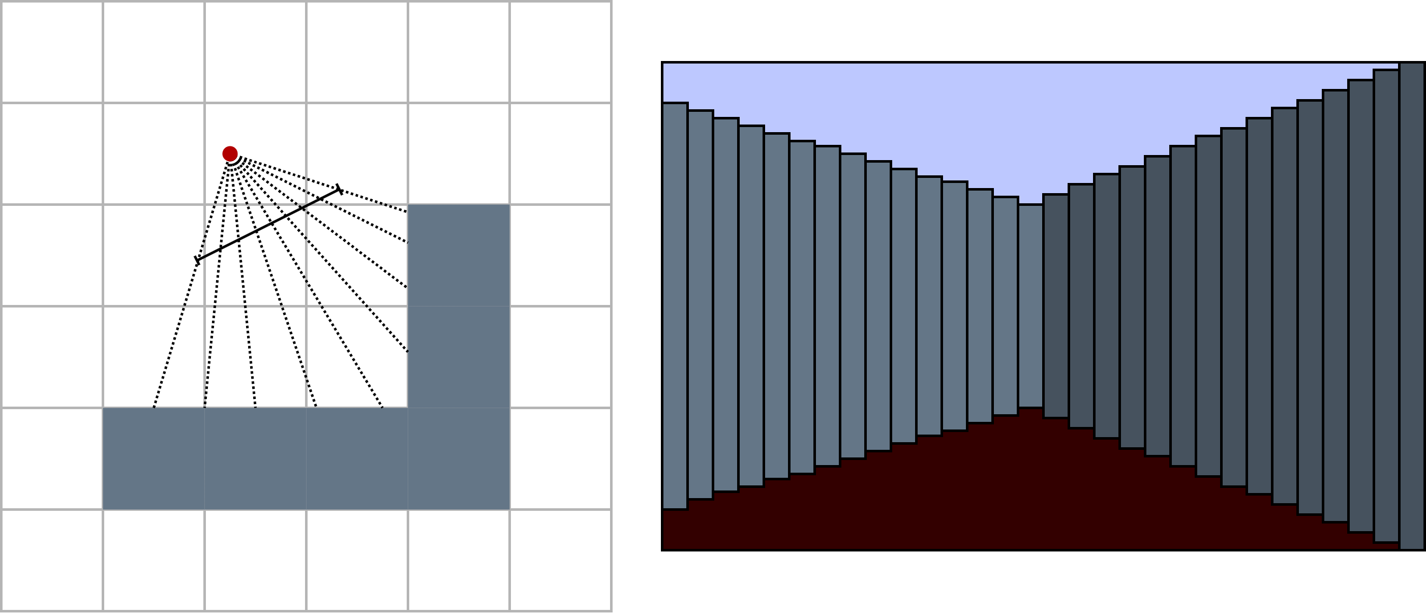
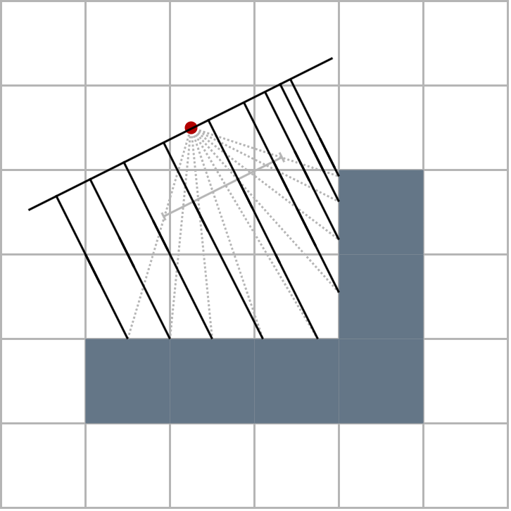
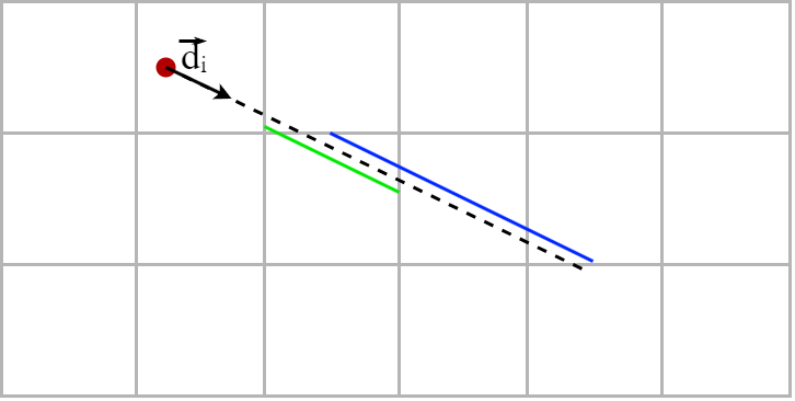
To display what the player sees, rays are cast from the player outward until they encounter a wall. The length of the ray corresponds to the distance between the player and the wall, which allows determining the wall’s height to be displayed on the screen. In the figure below, you can see that rays are sent throuth the field of view of the player. Their length determines the height of the wall strips that are drawn on the right.
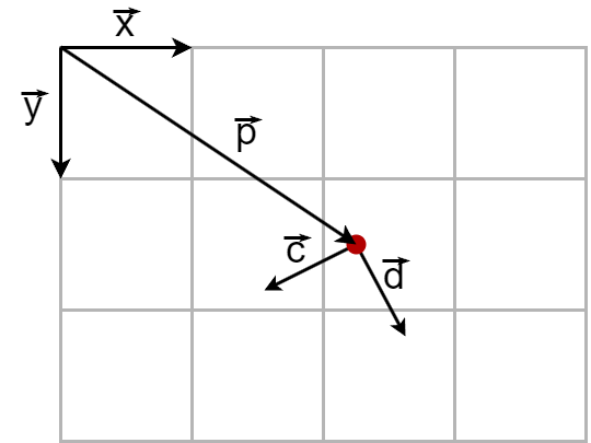
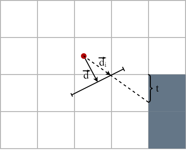
Let’s define our game space a bit more clearly. The red point represents the player. Their position in the game space is marked by the vector \(\vec{p}\). The direction in which the player is looking is represented by the unit vector \(\vec{d}\). Lastly, the vector \(\vec{c}\) is orthogonal to \(\vec{d}\).
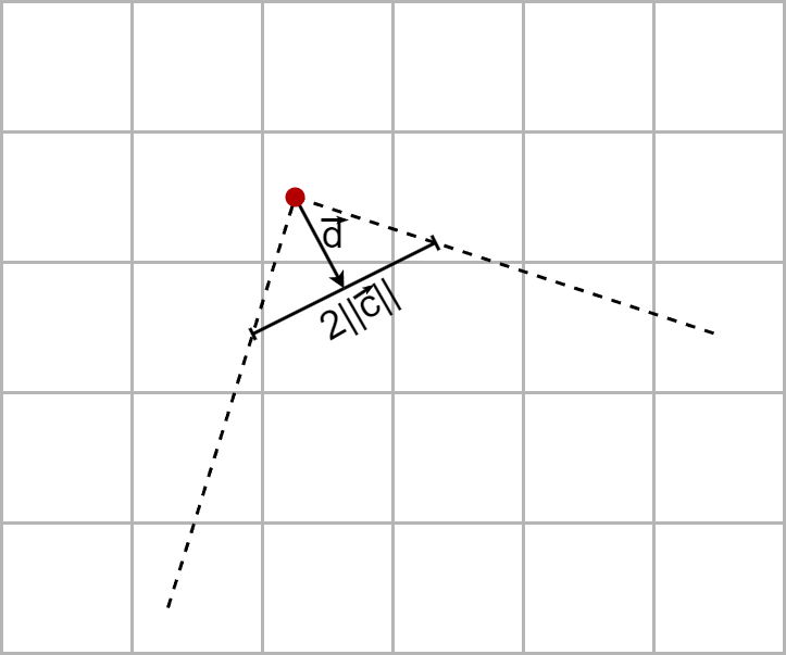
Vectors \(\vec{d}\) and \(\vec{c}\) together form another orthogonal basis, known as the camera’s basis. The projection plane for the player’s vision is directed by vector \(\vec{c}\) and centered on \(\vec{d}\). In the image below, you can see the camera’s projection plane as well as the two rays at the edges of the player’s field of vision. Note that the norm of vector \(\vec{c}\) determines the width of the player’s field of vision. The width of the field of view is equal to two times the length of the vector \(\vec{c}\).
How to send Rays
Now that we have properly defined our game space, let’s see how to cast the rays. A simple and fast approach is to send as many rays as the width of the game window in pixels. The direction of each ray can be calculated vectorially. Let’s denote \(w\) as the width of the window in pixels; then, the direction of the \(i^{th}\) ray starting from the left is:
\[\vec{d_{i}} = \vec{d} + \left( \frac{2i}{w} - 1 \right) \vec{c}\]With this formula, the rays are uniformly sent on the projection segment. Because a mistake not to make is to send the rays by uniformly splitting the angle of vision. By proceeding in this way, the rays are more concentrated on the middle of the projection plane and less on the edges, which will later on distort the final rendering on the screen. Moreover it is much easier to reason and calculate with vectors than with angles !
How to compute the rays’ length
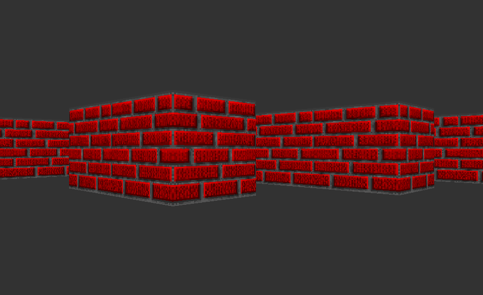
By carefully watching the first image, you may notice that something is wrong. On the screen the slope of the walls is regular, the height of the two wall slopes evolve linearly along the width of the screen. However, on the left, the ray lengths do not appear to vary accordingly.
And yes, we do have a problem, if we consider that the height of the strips of the wall is simply inversely proportional to the length of the associated rays, we obtain on the screen a distortion known as the fisheye effect!
To solve this problem, we must consider not the Euclidean length of the rays (distances between the player and the wall) but rather the distance between the wall and the projection plane. And we know that the distance between a point (the intersection of the ray and the wall) and a straight line (plane of projection) is equal to the perpendicular distance between that point and the line.
Let’s see how to calculate the perpendicular distance noted \(r_{prep}\) from the Euclidean length of the rays noted \(r\). If we note \(\theta\) the angle formed by the vectors \(\vec{d}\) and \(\vec{d_i}\), we notice that we find this same angle against the wall.
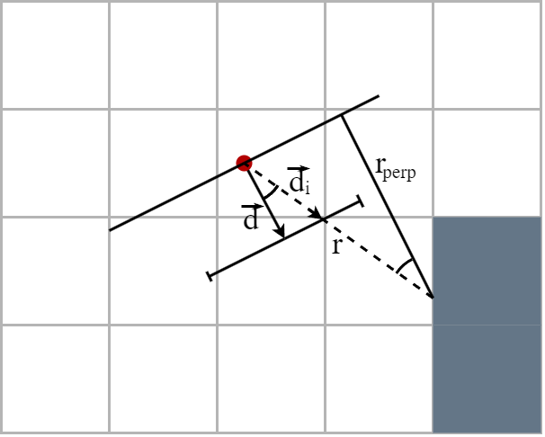
And because \(\vec{d}\) is a unit vector, we have
\[r_{perp} = \frac{r}{\|\vec{d_i}\|}\]Now that we know exactly what to calculate, let’s see how to do it.
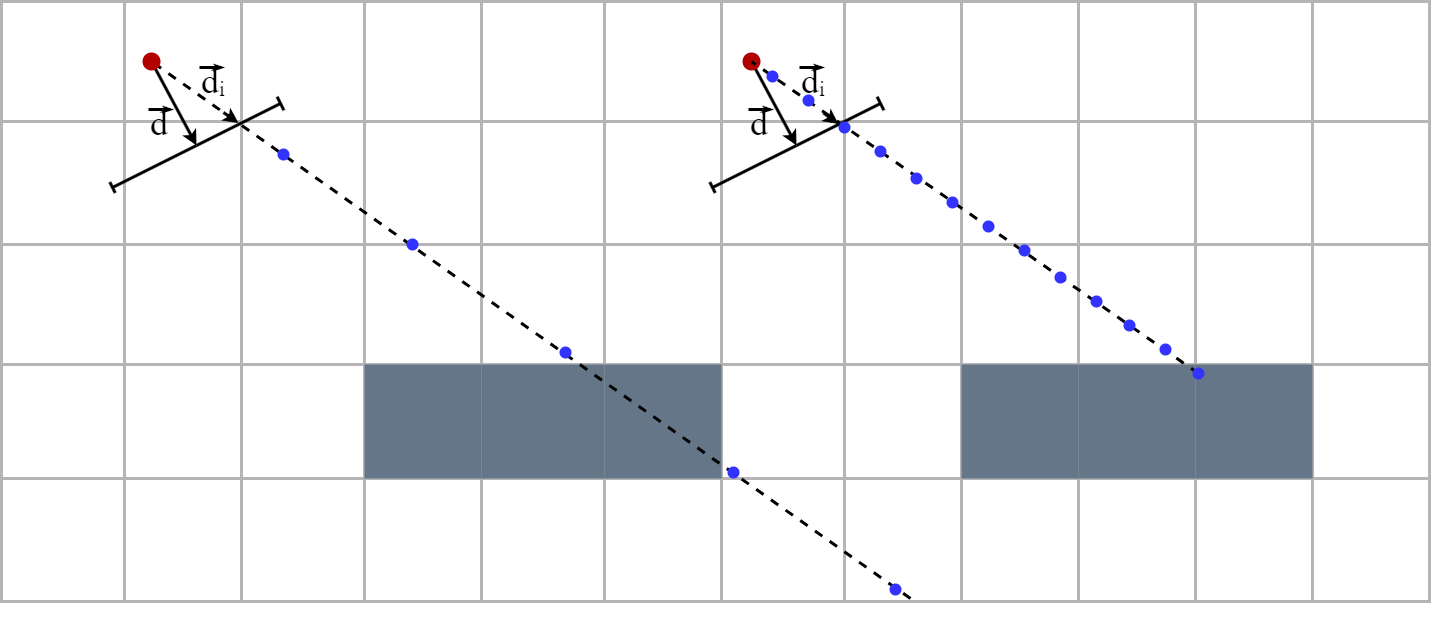
A naive approach is to start with a ray of zero length and gradually lengthen it until you encounter a wall. The problem with this method is that if the elongation is greater than the thickness of a wall, there is a risk of crossing a wall without detecting it. On the other hand, if the elongation is too small the algorithm will be unnecessarily long…
The DDA algorithm
DAA stands for Digital differential analyzer. It follows the naive idea described earlier but adjusts the elongation so that it moves from intersection to intersection on the grid. Since the walls are squares of size of a grid cell, we only need to verify the presence of a wall at the intersection points!
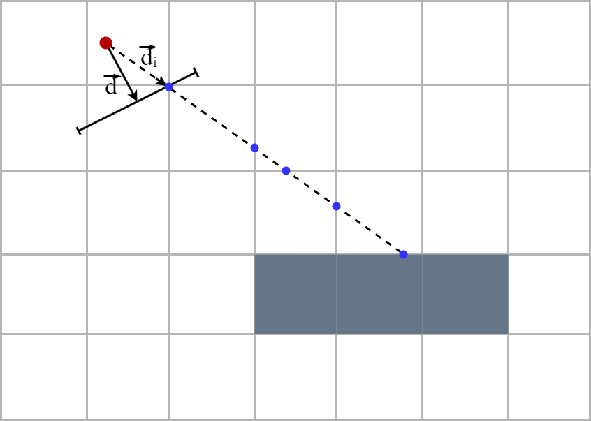
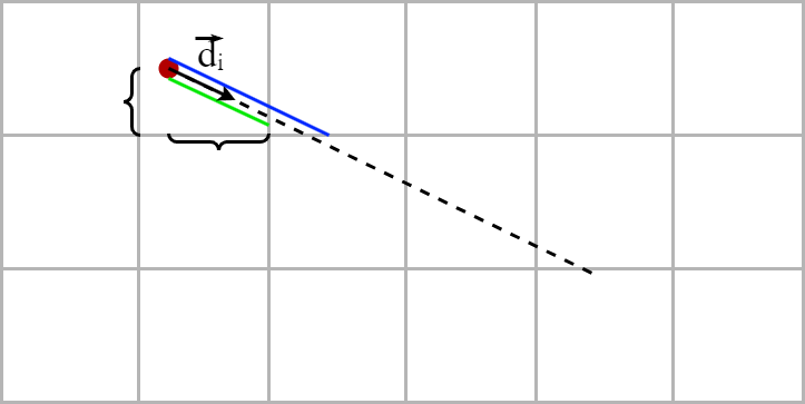
The key to the DDA algorithm is tha fact that the length of the ray between two parallel grid lines is constant. For each ray direction, we calculate the distance that the ray have to travel to advance one cell horizontally (in green) as well as the distance that the ray have to travel to advance one cell vertically (in blue).
The lengths of these segments are
\[\color{green}{u_x} = \frac{\|\vec{d_i}\|}{|\langle \vec{d_i}, \vec{x} \rangle|} \hspace{2em} \text{and} \hspace{2em} \color{blue}{u_y} = \frac{\|\vec{d_i}\|}{|\langle \vec{d_i}, \vec{y} \rangle|}\]Remember, we’re looking for \(r_{perp}\), so no need to mutilate with \(\vec{d_i}\) if it’s to do the division later!
There remains a small problem, the player is not necessarily on an intersection of the grid so it is necessary to start from an offset which is calculated by multiplying \(u_x\) and \(u_y\) by the distance between the player and the next row and column.
Then we iterate the extensions. In order not to confuse, we separate the progression of the ray in two. The green ray which extends from column to column and the blue ray which extends from row to row. We must lengthen each time the shorter of the two rads. To know when to stop, we define a control cell which is initially placed on the player’s cell. At each lengthening, the control cell moves horizontally or vertically depending on whether the blue or green ray has been lengthened. When the control cell detects a wall, it means that the ray which has been extended has passed through a wall. We remove the last elongation to this ray and we obtain the distance we were looking for!
Here is the algorithm in c++
constexpr int w = 1080;

class Player {
  public:
    float p_x;
    float p_y;

    float d_x;
    float d_y;

    float c_x;
    float c_y;
};

class Game {
  public:
    bool collide(int cell_x, int cell_y);
    void raycast();
    Player player;
    float perp_rays_lenght[w];
}

void Game::raycast() {
  for (int i=0; i<w; i++) {
    // direction step
    int step_x = 0;
    int step_y = 0;

    // x (green) and y (blue) rays' length
    float x_ray_length = 0;
    float y_ray_length = 0;

    // x coord of the ray in the camera plane in [-1,1]
    float camera = 2.f * i / w - 1.f;

    // ray direction
    float ray_dir_x = player.d_x + player.c_x * camera;
    float ray_dir_y = player.d_y + player.c_y * camera;

    // ray lengths per x,y step
    // we don't mutiply by the norm of ray_dir to avoid fisheye effect
    float u_x = std::abs(1.f / ray_dir_x);
    float u_y = std::abs(1.f / ray_dir_y);

    // controle cell coordinates initialy at the player location
    int control_cell_x = (int) player.p_x;
    int control_cell_y = (int) player.p_y;

    // add the initial offsets to rays
    // and find out in which direction the control_cell must move
    if (ray_dir_x > 0) { // we look at west
      x_ray_length += u_x * (1.f - (player.p_x - control_cell_x));
      step_x = 1;

    } else if (ray_dir_x < 0) { // we look at east
      x_ray_length += u_x * (game->player.p_x - control_cell_x);
      step_x = -1;
    }

    if (ray_dir_y > 0) { // we look at south
      y_ray_length += u_y * (1.f - (game->player.p_y - control_cell_y));
      step_y = 1;

    } else if (ray_dir_y < 0) { // we look at north
      y_ray_length += u_y * (game->player.p_y - control_cell_y);
      step_y = -1;
    }

    // to remember which ray we last lengthened
    char collision_side;

    while (true) // this is scary !
    {
      // lengthen the shortest ray and move the conrol cell
      if (x_ray_length < y_ray_length) {
        x_ray_length += u_x;
        control_cell_x += step_x;
        collision_side == 'x'
      }
      else {
        y_ray_length += u_y;
        control_cell_y += step_y;
        collision_side == 'y'
      }
      if (collide(control_cell_x, control_cell_y)) {
        break;
      }
    }

    if (collision_side == 'x') {
      perp_rays_lenght[i] = x_ray_length - u_x;
    } else {
      perp_rays_lenght[i] = y_ray_length - u_y;
    }

  }
}
Let’s draw the walls
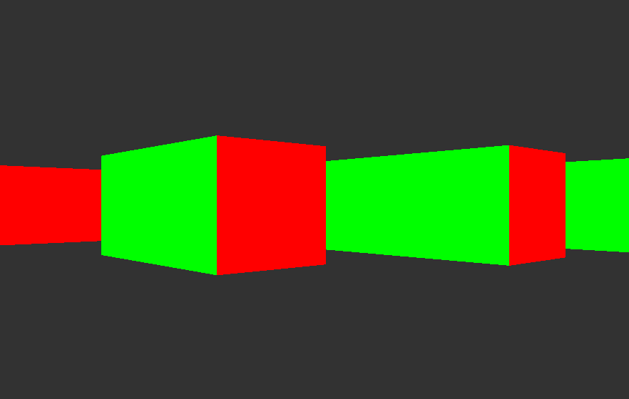
Now that we have the lengths of the rays, all that remains is to display the walls! Assuming the player’s eyes are half as high as the walls, we can display all the wall strips centered vertically on the screen. We put a different color for each sides to see better and here we are!
Hovertank 3D also had uniformly coloured walls, but we’ll see that it’s not very complicated to apply a texture.
Let’s start with a square image which will be the texture of a piece of wall. The idea is also to cut this texture into vertical strips and then to stretch or contract them according to the height of the strip of wall that is rendered on the screen.

To know which stip of the texture needs to be apply on the screen, we have to compute the distance between the point of impact of the ray on the wall end the left side of that piece of wall. Let’s note this distance \(t\).
Given that the texture is \(N\times N\) pixels, the corresponding band to be displayed on screen is \(\lfloor tN\rfloor\). By using the same scaling technique for height, you can get textured walls!