Retro Raycasting game - part 3
A few weeks ago I wanted to code a 3d video game in C++. To share my experience, I decided to write about the rendering technique I used. This post follows part 1 where I explained how to render textured walls and part 2 where I talked about the rendering of the floor and the ceiling.
To make you enjoy my game (still in development) I compiled it with emscripten which gives an executable in webassembly! Feel free to play it here.
At this point, the game is still fairly empty, so we’re going to look at how to add objects. The idea is to have an image with coordinates. The goal is to display this image at the right coordinates in the game, at the right size and at the right height on the screen to give the illusion that it’s standing on the ground.
The basic Idea
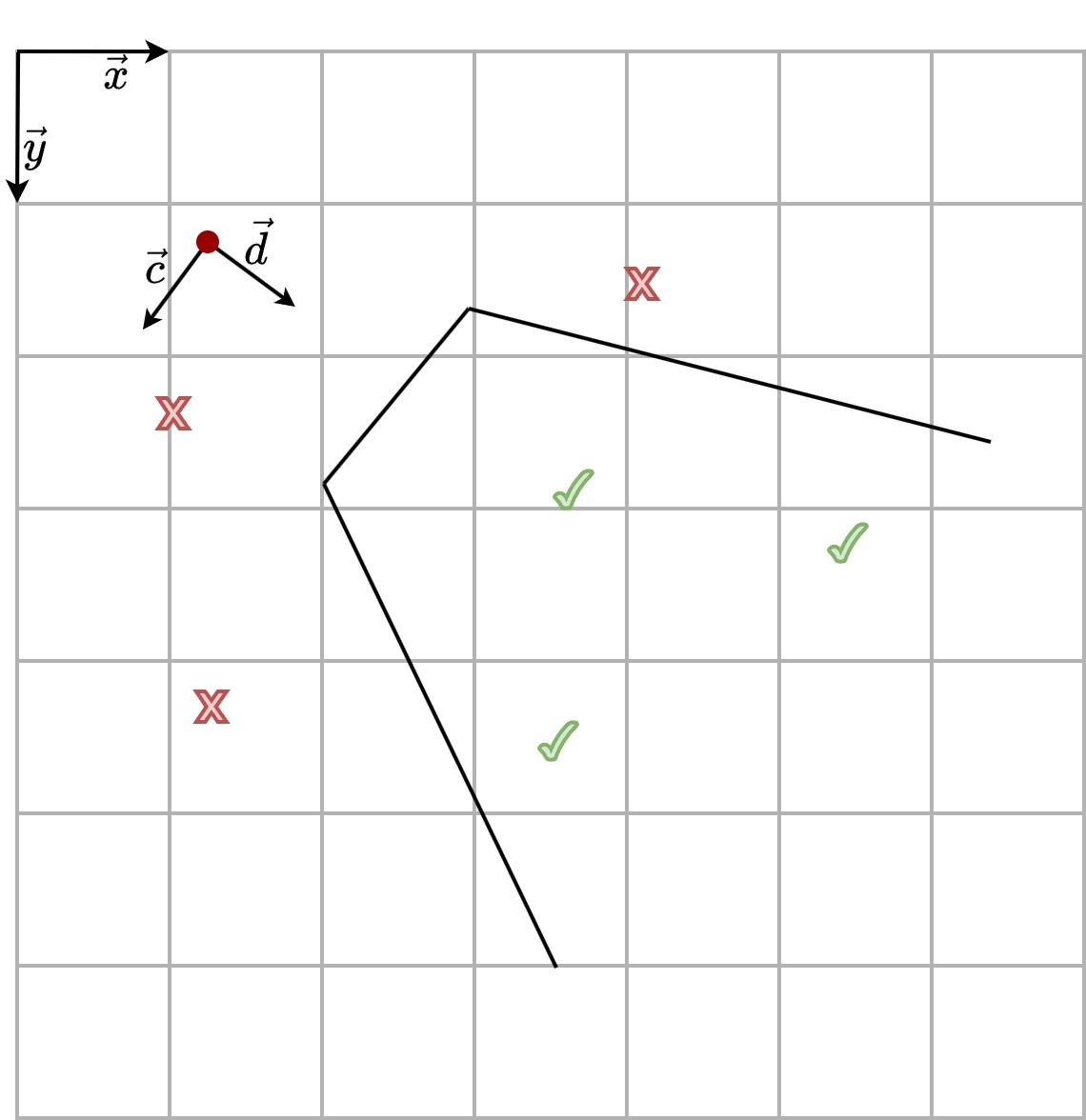
This time we’re not sending rays to determine which objects in the field of view should be displayed, instead we’re going to loop over all the objects in the game and determine whether they should be rendered. To do this, we need to know the position of the object relative to the player by changing the coordinate system. In the player’s coordinate system, an object is displayed on the screen if its y coordinate is positive and the absolute value of its x coordinate is less than the width of the field of view at that distance.

Green ticks on the figure are exemple of position where objects must be rendered. Red cross are exemple of position that are outside the field of view of the player and must not be rendered.
The only difficulty is figuring out how to calculate the coordinates of the objects relative to the player.
Again, A bit of geometry
The condition for displaying or not an object on the screen is based on its coordinates relative to the player. Let \(\vec{v}_{xy}\) denote the coordinate vector in the \((\vec{x},\vec{y})\) basis of any object, and \(\vec{v}_{cd}\) its coordinate vector in the \((\vec{c},\vec{d})\) basis. Then we have
\[\vec{v}_{xy} = M \vec{v}_{cd}\]with
\[M = \left( \begin{array}{cc} \vec{c}\cdot\vec{x} & \vec{d}\cdot\vec{x} \\ \vec{c}\cdot\vec{y} & \vec{d}\cdot\vec{y} \\ \end{array} \right)\]So, we can calculate \(\vec{v}_{cd}\) by matrix inversion.
\[\vec{v}_{cd} = M^{-1}\vec{v}_{xy} = \frac{1}{\vec{c}\cdot\vec{x} \ \ \vec{d}\cdot\vec{y} - \vec{c}\cdot\vec{y} \ \ \vec{d}\cdot\vec{x}} \left( \begin{array}{cc} \vec{d}\cdot\vec{y} & -\vec{d}\cdot\vec{x} \\ -\vec{c}\cdot\vec{y} & \vec{c}\cdot\vec{x} \\ \end{array} \right) \vec{v}_{xy}\]The coordinates of the vector \(\vec{v}_{cd}\) give us the values \(\frac{\vec{v} \cdot \vec{d}}{\|\vec{d}\|}\) and \(\frac{\vec{v} \cdot \vec{c}}{\|\vec{c}\|}\).
The rendering strategy
Alright, we now have the coordinates of all the objects relative to the player. Let’s now see how to display them correctly within the player’s field of view.
The first thing to do is to sort the objects by their perpendicular distance to the player. This helps remove objects with a negative distance (those behind the player) and ensures that the farthest objects are rendered first in case multiple objects are aligned with the player. (An object closer to the player should be displayed in front of more distant objects.)
The second point to consider is what happens if an object is behind a wall, or worse, behind a corner of a wall. We would like to display only the parts that are actually visible from the player’s eyes. To solve this problem, we will cut the images corresponding to the objects into vertical strips. For each strip of each object, we compare the perpendicular distance of that strip with the perpendicular distance of the aligned strip of wall. If the strip of wall is closer, we do not display the strip of the object’s image; on the contrary, if the object is closer than the strip of the wall, then we display the strip of the object’s image over the wall.
The third point: the strategy we have chosen to display objects requires cutting their image into strips, but the challenge now is to determine the position of these strips on the screen…
Where to draw?
To determine where to draw the object’s image on the screen, we need three distances in pixels: the height of the image \(h_0\), the distance from the top edge of the screen \(y_0\), and the distance from the left edge of the screen \(x_0\).

– \(h_0\) –
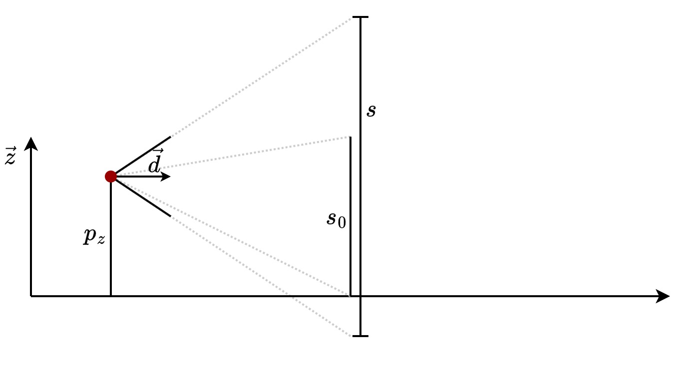
Let’s first try to determine the size of the objects to be drawn on the screen, denoted as \(h_0\). Let \(s_0\) be the height of the object in the game. In Part 1, we constructed walls whose height is equal to the inverse of their perpendicular distance to the player. Similarly, here, the height of the objects is inversely proportional to their perpendicular distance to the player. For example, for an object with the same height as a wall \(s_0\) is equal to \(1\). Finally, let \(s\) be the height of the player’s field of view at the level of the object. Therefore, we have \(s=\frac{ \vec{v}_{cd} \cdot \vec{d}}{\| \vec{d} \| }\).

To switch from the scene’s point of view to the screen, we just use cross-multiplication!
\[h_0 = \frac{hs_0}{s} = \frac{hs_0\|\vec{d}\|}{\vec{v}_{cd} \cdot \vec{d}}\]Well, we know the size of the image to display but we still don’t know where to display it.
– \(y_0\) –
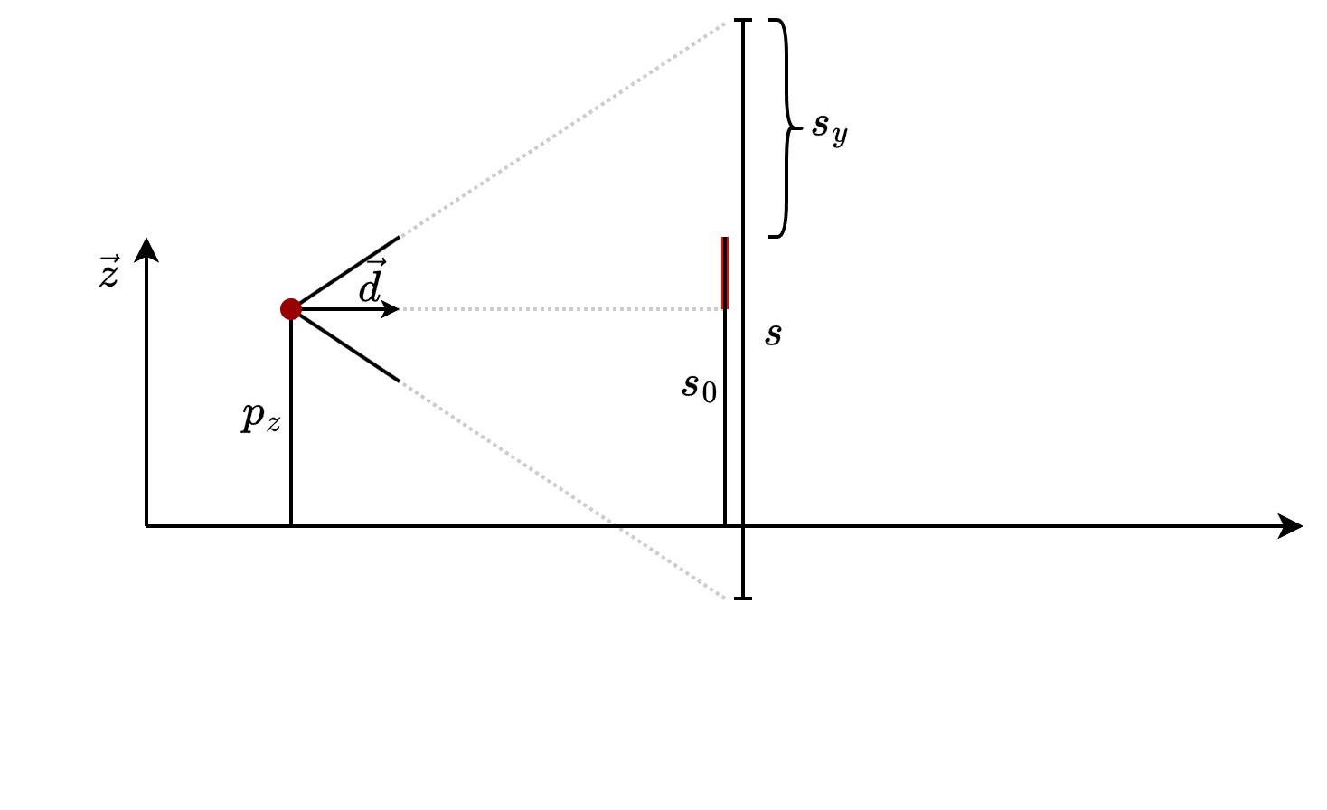
To calculate \(y_0\), we need \(s_y\), the distance between the top of the player’s field of view and the top of the object. The trick is to see that the length of the red segment in the image is equal to \(s_0 - p_z\). So, we easily find that \(s_y = \frac{s}{2} - (s_0 - p_z)\).

Again, we use cross-multiplication to go from scene to screen
\[y_0 = \frac{h}{s}s_y = \frac{h}{2} - \frac{h}{s}(s_0 - p_z)\]Note that it may happen that \(y_0 < 0\) or \(y_0 + h_0 > h\). In such cases, the object extends beyond the field of view, and the image must be truncated.
– \(x_0\) –
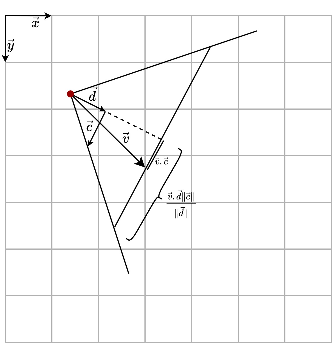
For \(x_0\), we’ll look at the scene seen from above, as illustrated below.

The distance between the object and the center of the scene is \(s_x = \vec{v} \cdot \vec{c}\), and the half-width of the field of view at the object is \(l = \frac{\vec{v} \cdot \vec{d} \|\vec{c}\|}{\|\vec{d}\|}\).
So, we found the following expression for \(x_0\) thanks to cross-multiplication
\[x_0 = w \frac{l+s_x}{2l} = \frac{w}{2}\left( 1 + \frac{\vec{v} \cdot \vec{c}\|\vec{d}\|}{\vec{v} \cdot \vec{d}\|\vec{c}\|} \right)\]The code
class Player {
  public:
    float p_x;
    float p_y;

    float d_x;
    float d_y;

    float c_x;
    float c_y;
};

struct in_game_object_t {
  Uint32* texture;
  int texture_width;
  int texture_height;

  float v_xy_x;
  float v_xy_y;

  float v_cd_c;
  float v_cd_d;
}

class Game {
  public:
    Player player;
    float perp_rays_lenght[w];
    Uint32 scene_pixels[w*h];
    std::list<struct in_game_object_t*> in_game_objects;
}


void draw_objects(Game* game) {

  float inv_det = 1.0 / (
    game->player.c_x * game->player.d_y -
    game->player.d_x * game->player.c_y
  );

  for (
    auto object = game->in_game_objects.begin();
    object != game->in_game_objects.end();
    object++
  ) {
    float delta_x = (*object)->v_xy_x - game->player.p_x;
    float delta_y = (*object)->v_xy_y - game->player.p_y;
    (*object)->v_cd_c = inv_det * (
      game->player.d_y * delta_x - game->player.d_x * delta_y
    );
    (*object)->v_cd_d = inv_det * (
      -game->player.c_y * delta_x + game->player.c_x * delta_y
    );
  }

  // sort the entities to display the furthest before the closest
  game->in_game_objects.sort(
    [] (Entity* a, Entity* b) {return a->v_cd_d > b->v_cd_d;}
  );

  for (
    auto object = game->in_game_objects.begin();
    object != game->in_game_objects.end();
    object++
  ) {

    // if the object is too close or behind the player, skip it
    if ((*object)->v_cd_d < 0.5f) continue;

    int x_0 = int(0.5 * w * (1.0 + (*object)->v_cd_c / (*object)->v_cd_d));
    int h_0 = int(s * h / (*object)->v_cd_d);
    int w_0 = h_0 * (*object)->texture_width / (*object)->texture_height;
    int y_0 = int(h / 2 - h * (s - 0.5f) / (*object)->v_cd_d);

    float texture_step_x = (float) (*object)->texture_width / (float) w_0;
    float texture_step_y = (float) (*object)->texture_height / (float) h_0;

    for (int i=0; i < w_0; i++) {

      int x = x_0 - w_0 / 2 + i;

      // if the image strip is outside the player's view or behind a wall, skip it
      if ( x < 0 || x > game->width ) continue;
      if (camera_y > game->raycaster.rays_lenght[x]) continue;

      int tex_x = i*texture_step_x;

      // be careful not to draw above or below the screen
      h_0 = (h_0 + y_0 >= h) ? h - y_0 - 1 : h_0;
      for (int y = y_0<0 ? -y_0 : 0; y < h; y++) {
        // select and draw pixel per pixel
        int tex_y = y*texture_step_y;
        Uint32 color = (*object)->texture[tex_x + tex_y*(*object)->texture_width];
        game->scene_pixels[x + (y + y_0)*w] = color;
      }
    }
  }
}